The IPH Experiment at Sacramento

In the mid 1970s, a solar industrial process heat experiment was carried out at a Campbell Soup Company plant in Sacramento, CA. The system was designed to supply 75% of the energy needed to produce hot water at 85-90 C for can washing to one of the production lines producing chicken noodle soup. It is described briefly on pages 630 - 631 of Solar Engineering of Thermal Processes (Duffie and Beckman, 1991).
In the canning plant, cans are washed both before and after filling. Thus the hot water has to be of potable quality. The plant has to meet all of Campbell's quality standards and conform to all applicable regulations of USDA, FDA, EPA, OSHA, ANSI, and other regulatory agencies that deal with food processing.
The water flow rate for the can washing operation is 12.5 gallons per minute at a temperature of 85 to 90 C. Hot water must be provided continuously at this rate for two shifts (7AM to 11PM) five days a week. The energy to heat the water came from arrays of flat plate collectors and linear concentrators in series, and an auxiliary steam heater. The solar energy system was designed to provide all of the hot water for the line at mid-day on a peak June day; thus at most times the collectors could supply only part of the load and auxiliary energy (steam) was used for the balance.
The two collector arrays were arranged in series. Mains water went to the flat plate collectors first, then to the linear concentrators, and then to the storage tank. The flat plate collectors had an aggregate area of 4,455 ft2. and were sloped at 25o to the south. The concentrators had an aggregate aperture area of 2880 ft2 and continuously tracked the sun about horizontal east-west axes. The storage unit was a 19,000 gallon vertical cylindrical insulated tank, located out-of-doors.
(During the experimental operation, there were more shut-downs than anticipated. Some of these were of sufficient duration that it was not possible to use or store energy from the collectors.)
Little specific information is available on the system beyond that noted above. We do not have the details of how the system was controlled, what the collector characteristics were, and what tank specifications were. However, based on other literature and on experience, we can make assumptions that must come close to the circumstances of the experiment. The parameters listed below (based on these logical assumptions), together with the data we have, provide the necessary information to simulate the system.
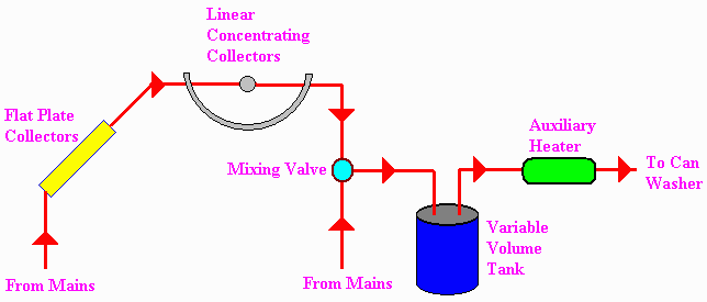
System V: Variable Storage Volume System (VVTANK.TRD in TRNSED)
In this system the quantity of water in the tank can vary with time. Water from the mains goes through the collector and to the tank whenever energy can be collected. Heated water from the collector arrays entered the tank at a fixed flow rate of 12.5 gpm. Hot water is pumped from the tank through the auxiliary heater and to the can washers at a fixed rate of 12.5 gpm.
System V is:

Controls on this system are designed to run with the tank at the minimum level as far as possible. This allows hot water to accumulate when the collectors can operate and when there is no load. There is flow to the collectors whenever energy can be collected, unless the tank is full and there is no load flow.
If there is no flow through the collectors, if the level in the tank reaches the minimum level, and if there is flow to the load, water from the mains enters the tank at 12.5 gpm.
If there is no load flow, if the tank is not full, and if the collectors are operating, heated water from the collectors accumulates in the tank until the tank is full. When the tank is full and there is no load flow, there can be no flow to the collectors.
If there is no load flow, if there is no collector flow, and if the tank is empty, it stays empty.
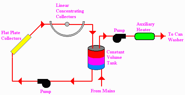
SYSTEM F: Constant Storage Volume System (CVTANK.TRD in TRNSED)
This system differs from that installed at the Campbell plant in one major respect. The storage tank is assumed to be full at all times, and water can be circulated through the collector loop whenever energy can be collected and through the (open) load circuit whenever there is a load.
System F is:

Controls can be assumed to operate as follows: The collector loop is operated as long as there is enough radiation to produce a temperature rise across the collector arrays. The flow rate is fixed at 12.5 gpm. If the output temperature from the collectors exceeds 98 C, the concentrators are defocussed so that there is no useful gain from that part of the collector system but the losses from that part continue.
Water is pumped from the tank to the auxiliary heater and load at a rate of 12.5 gpm whenever the can washer operates. Makeup water is supplied from the mains at a temperature of 19 C to the bottom of the tank whenever the washer operates.
Component and System Data Common to Both Systems:
* The flat plate collectors had an aggregate area of 4,455 ft2, and were mounted on existing skylights. They faced south at a slope of 25o. They had one cover, and the absorbing surface was flat black. Assume the following:
an = 0.91, e = 0.92
Plate material: Aluminum, thickness = 0.00056 m.
Back insulation: thickness = 0.062 m, k= 0.0303 W/moC
Cover: KL = 0.0100
Plate to cover spacing = 0.027 m.
Edge losses are negligible.
* The concentrators were linear parabolic troughs, tracking continuously about horizontal east-west axes. The aperture area was 2880 ft2. Assume the following:
Receiver is steel tube with black chrome plating. a = 0.93, e = 0.24
Cover is a cylinder of borosilicate glass. t = 0.83
Area concentration ratio = 35.
Focal Length = 3.05 m; Aperture = 3.5 m.
Loss Coefficient = 15 W/m2C (based on absorber area) at operating temperatures.
Product rta = 0.69
* The storage tank had a capacity of 19,000 gallons. It was a vertical cylindrical tank located outdoors. It was well insulated and was designed to be well stratified. Assume the following:
UA = 450 W/C.
It has been assumed for this system that heat losses from piping are included in the losses from the collectors and tank. Note that these losses can be significant in very large industrial systems because of distances between collector fields and end use.
* These parameters lead to the parameters entered in the TRNSED input files for the two systems.
You can change the parameters in the input files. For example, you can change the tank volume or area of a collector by changing the appropriate fields in the input files.
Hourly weather data for Sacramento are generated by the TRNSYS weather generator component during the TRNSYS simulation.
Hints for Using the Demonstration
As demonstrated by this example, TRNSYS enables the user to look at a system like the Campbell experiment - with hindsight - and see how the system should have worked and how it would have worked if some alternative design decisions had been made. With this downloadable demonstration , you can use TRNSYS via TRNSED to simulate the systems, to evaluate their operation, and then modify the systems in ways that you might suggest, to determine the performance of the modified systems.
You might compare the performance of the constant volume and variable volume systems as represented in the TRNSED input files (cvtank.trd and vvtank.trd, respectively). Then you might modify the systems as you think appropriate. You could compare how the systems would operate if all the collectors were flat plate or all of concentrator design. (You can replace one type of concentrator by the other, but due to physical limitations the total collector area can not exceed the sum of 4455 and 2880, or 6435 ft2.) You could assess the effects of storage capacity, or the effect of going to a selective surface on the flat plate collector (this is easy now, but was not so 25 years ago!).