TYPE 75: ELECTRIC
CONVERTER
General Description
This subroutine models a DC/AC inverter and a DC/DC converter
after /1/.
Nomenclature
- mode - 1 = Connected to the electric power net 2 =
Connected to a load
- Z - Power efficiency
of the converter or inverter
- Pn - Characteristic output power for one
module
- P - Power ; mode = 1 : Input power known, mode = 2 :
Output power known
- P0pn - Idling constant for a converter or
inverter module (P0pn = P0/Pn,
P0 [W] power loss when there is a voltage over
the inverter or converter)
- Us - Set voltage for a module
- Ripn - Inner resistance constant for a Module
of converter or inverter (Ripn = Ri*Pn, Ri [Ohm] Inner
resistance for a module)
- mp - Number of parallel connected modules
- Uin - Voltage in to the converter or inverter
- Uout - Voltage out of the converter or
inverter
- Iout - Current out of the converter or
inverter
- Pout - Power out of the converter or inverter
- Iin - Current in to the converter or inverter
- Pin - Power in to the converter or inverter
- Ploss - The power loss in the converter or
inverter
-
Mathematical Description
The power loss for both modes is calculated with this
equation:

The inverter/converter can have either output or input power
as input for the calculations (output if the system is connected
to a load or input if the system is connected to the electric
power net).
The converter/inverter is disconnected when the input voltage,
output voltage or power is zero.
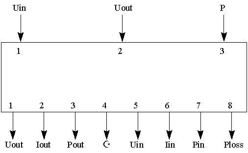
TRNSYS Component Configuration
PARAMETER NO. DESCRIPTION
- 1 mode - 1 = Connected to the electric power net 2 =
Connected to a load
- 2 Pn - Characteristic output power for one
module
- 3 P0pn - Idling constant for a converter or
inverter module (P0pn = P0/Pn,
P0 [W] power loss when there is a voltage over
the inverter or converter)
- 4 Us - Set voltage for a module
- 5 Ripn - Inner resistance constant for a
Module of converter or inverter (Ripn = Ri*pn, Ri [Ohm]
Inner resistance for a module)
- 6 mp - Number of parallel connected modules
-
INPUT NO. DESCRIPTION
- 1 Uin - Voltage in to the converter or
inverter
- 2 Uout - Voltage out of the converter or
inverter
- 3 P - Power ; mode = 1 : Input power known, mode = 2 :
Output power known
OUTPUT NO. DESCRIPTION
- 1 Uout - Voltage out of the converter or
inverter
- 2 Iout - Current out of the converter or
inverter
- 3 Pout - Power out of the converter or
inverter
- 4 Z - Power
efficiency of the converter or inverter
- 5 Uin - Voltage in to the converter or
inverter
- 6 Iin - Current in to the converter or
inverter
- 7 Pin - Power in to the converter or inverter
- 8 Ploss - The power loss in the converter or
inverter
-
Informational Flow Diagrams

References
/1/ Hermann Laukamp, Wechselrichter f9r Photovoltaik-Anlagen,
FhG-ISE Freiburg, 1988.
![]()
